Hardware
Mobile Ground Station
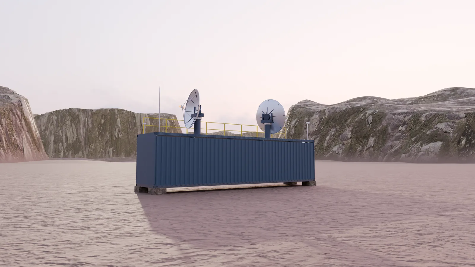
A complete ground station in an ISO 40 ft high-cube container. It ships by sea, sets up where it is needed and belongs to the country that hosts it.
The container
Moves and stacks like any container
- ISO 40 ft high-cube, 12 192 × 2 438 × 2 896 mm, with ISO corner castings and a CSC plate. It lifts, stacks and travels by container ship and truck.
- Ready for transit: dishes, phased-array panels, the lightning mast and the roof guard rail fold or come off.
- On site: it sits on a level concrete pad and connects through an end-wall gland plate to shore power, data and fibre.
- Host-country owned: the station belongs to the country that hosts it.
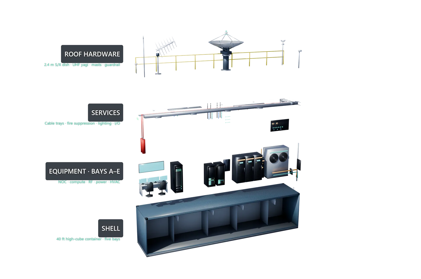
Inside
The five bays
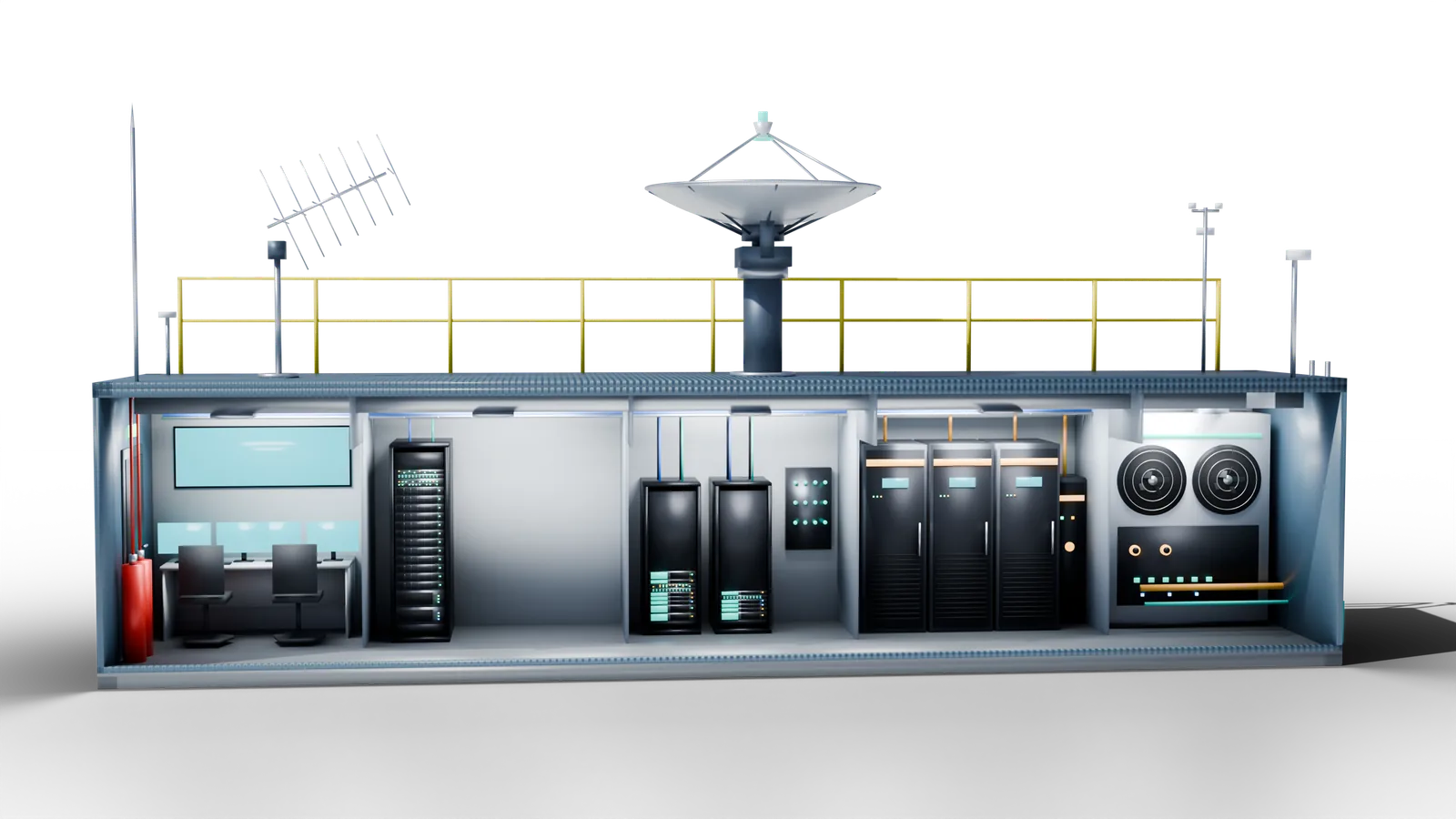
A
NOC
- Operator positions with dual monitors and a video wall
- The fire-suppression cylinders
- The personnel door
B
Compute
- A 42U rack against the back wall: GPU compute, storage chassis, network switch, patch panel and KVM
- Front-access equipment only
C
RF
- The RF rack: software-defined radio and modem chassis, up/down converters, LNA control, HPAs and a GPS-disciplined frequency and time reference
- A wall panel of RF connectors, with coax risers to the roof or the feed
D
Power
- LFP battery cabinets behind an automatic transfer switch, which moves between shore or generator power and the batteries with no interruption to the load
- An overhead DC busway
E
HVAC + I/O
- The HVAC cabinet, with a supply duct over the bays and a diffuser in each
- The I/O panel for shore power, data and fibre
Roof and site
Everything a station needs on site
- GNSS timing antenna
- Disciplines the station clock and timing reference.
- Weather station
- Wind data feeds the antenna stow logic.
- Lightning protection
- An air terminal on a mast that comes off for transit.
- CCTV
- A perimeter camera on a pole at the roof corner.
- Roof access
- A guard rail that comes off for transit, and an end-wall ladder.
- Fire and smoke
- Fire suppression with a nozzle in every bay, and a smoke detector in each.
- Cabling
- An overhead cable ladder, colour-coded orange for power, teal for RF and timing, and blue for data.
- Site connection
- A level concrete pad, and an end-wall gland plate for shore power, data and fibre.
Configurations
Six ways to build the station
Roof-mounted dishes and phased arrays for low-earth orbit, and ground-mounted dishes on their own foundation for GEO and MEO links.
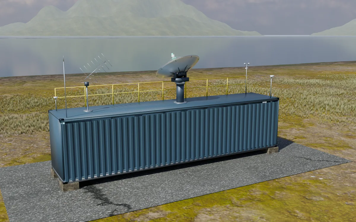
Render Unit 001 · POC
Single tracking dish
- 2.4 m S/X tracking dish that works one satellite per pass and folds for transit
- UHF/VHF crossed yagi on its own rotator for cubesat TT&C
- UHF
- S
- X
Render Core unit
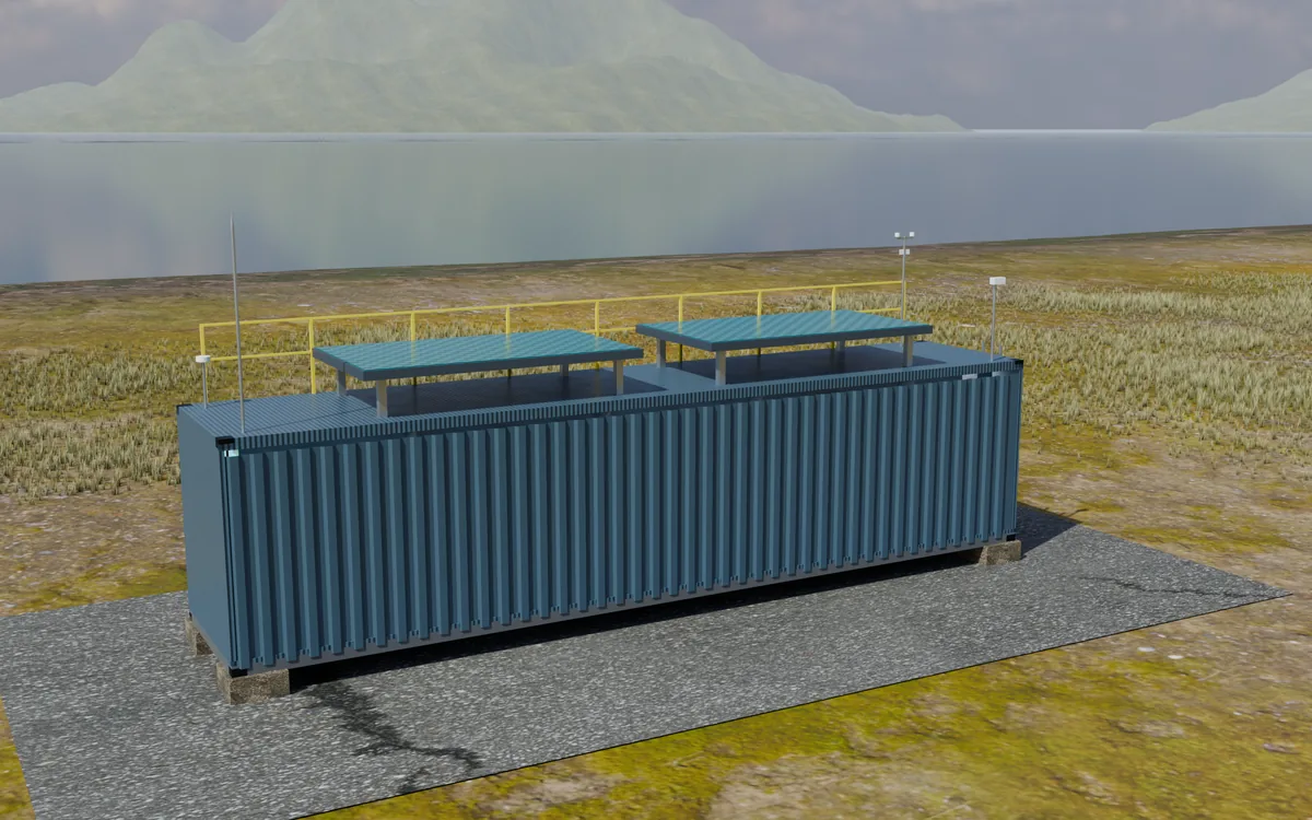
Phased-array primary aperture
- Dual phased-array panels on posts above the roof
- Multi-beam, with no moving parts
- Panels fold flat for transit
- UHF
- S
- X
Render Max satellites
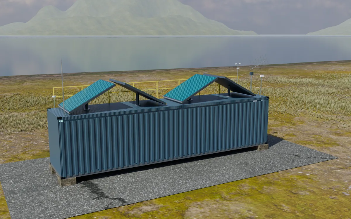
Multi-beam phased arrays
- Four S/X phased-array panels tilted north, south, east and west, plus UHF
- Several beams per panel: built for breadth of contact
- Panels fold flat for transit
- UHF
- S
- X
Render Max throughput
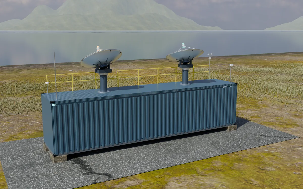
Ka + X high-rate dishes
- A 2.4 m Ka dish and a 2.4 m S/X dual-polarisation dish
- Built for raw downlink capacity for earth-observation operators
- S
- X
- Ka
Render GEO/MEO · 4.5 m
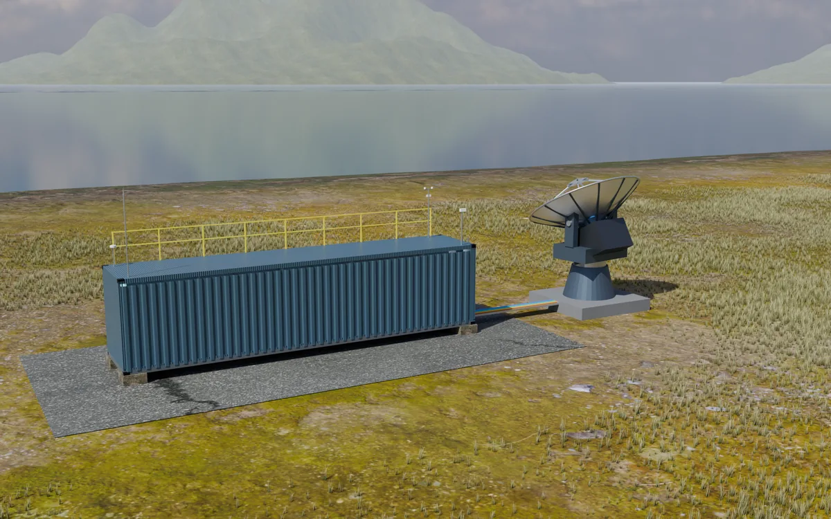
Ground-mounted dish
- 4.5 m dish on its own foundation beyond the container end
- Cassegrain feed cluster for S, X, Ku, Ka and L-band receive
- HPAs, LNAs and converters at the feed; power, RF and fibre back to the container by duct
- S
- X
- Ku
- Ka
- L rx
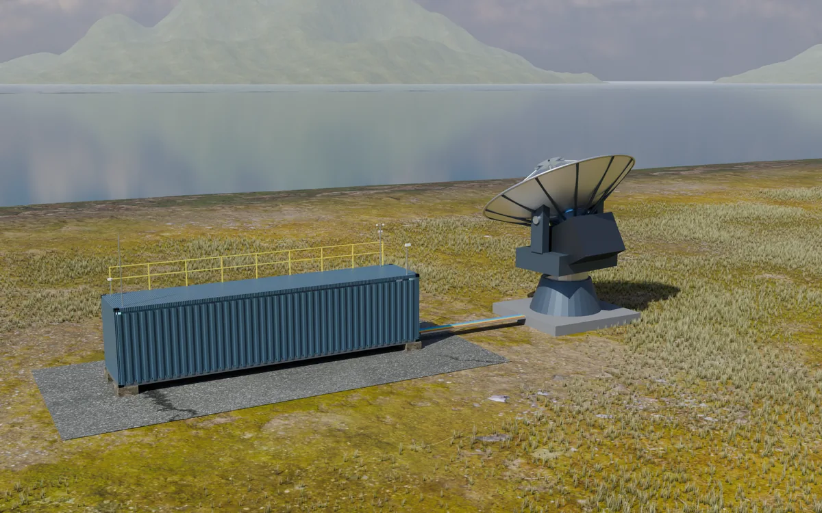
Render GEO/MEO · 7.3 m
Ground-mounted dish
- 7.3 m dish on its own foundation beyond the container end
- Cassegrain feed cluster for S, X, Ku, Ka and L-band receive
- HPAs, LNAs and converters at the feed; power, RF and fibre back to the container by duct
- S
- X
- Ku
- Ka
- L rx
Reference
Bands
| Band | Used for |
|---|---|
| UHF / VHF | Cubesat TT&C |
| S-band | Command and telemetry |
| X-band | TT&C and earth-observation downlink |
| Ku-band | Satellite links, GEO and MEO |
| Ka-band | High-rate links |
| L-band (receive) | GNSS and navigation signal monitoring |
Want the figures?
Every configuration has a full specification: rates, simultaneous contacts, satellites per day, downlink, power and reach. We share it with early-access partners, together with access to the 3D station viewer.